Executive Summary
Overview
Controlled reception pattern antennas (CRPAs) provide increased precision and robustness to positioning systems in navigation warfare (NAVWAR) environments. This page provides:
- An overview of GNSS and CRPA systems
- A description of how a CRPA system works
- A deep dive into GPS signals, beamforming, null steering, and arrays
- Methodologies for testing CRPA systems
- Spirent CRPA testing solutions
Introductory Principles
Figure 1. Modeled GPS satellite orbits using ephemeris data from October 2023
What is GNSS?
Global navigation satellite system (GNSS) is a broad term encompassing different types of satellite-based positioning, navigation and timing (PNT) systems used worldwide. GPS (Global Positioning System) is one type of GNSS.
Each GNSS satellite broadcasts a radio-frequency (RF) signal with precise PNT data. By the time GNSS signals reach the surface of the earth they are weak, making them susceptible to interference. Mission-critical GNSS-based systems must operate under all possible electromagnetic and environmental conditions.
To mitigate GPS-contested environments with jamming and spoofing—referred to as navigation warfare (NAVWAR)—advanced antennas called CRPAs are used with GNSS receivers to improve the detection, tracking, and recovery of signals.
What is a CRPA and why use it?
Controlled reception pattern antenna (CRPA) systems are used with GNSS receivers to enhance the reception quality of the desired signals and reject interference from undesired signals. The individual antennas that make up a CRPA are the antenna elements, and function together as an antenna array. These regularly-spaced antennas combine the radio signals to receive as a single steerable antenna. The outputs of the antenna elements are fed into the antenna electronics (AE) unit. In some newer receiver designs, the AE may be integrated together with the array elements.
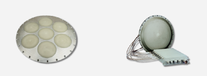
Figure 2. A representative CRPA with 7 antenna elements Figure 3. A CRPA connected to an antenna electronics (AE) unit
The number of antenna elements in a CRPA varies depending on the application. One common CRPA implementation is a 7-element design, with one center antenna and 6 surrounding it. For GNSS applications, the antenna array would typically be on top of a vehicle with the field of view pointing to the sky.
How does a CRPA work?
CRPA systems improve the GNSS receiver performance by using adaptive antenna array techniques:
- While a single-element antenna has a fixed reception pattern at a given frequency, an adaptive antenna array can create diverse antenna patterns based on how the array elements are combined.
- The AE controls the amplitude and phase of the radio frequency (RF) signals from the antenna elements and combines them in order to adapt the reception pattern. The resulting pattern is optimized so that the desired signals are amplified (via beamforming) while the interference signals are attenuated (via null steering).
- This controlled reception pattern enables the GNSS receiver to adaptively direct the CRPA’s beams at the desired signals and, at the same time, direct the CRPA’s nulls at the interference signals, thus preserving the GNSS signal tracking while minimizing interference and hence significantly mitigating hostile NAVWAR environments.
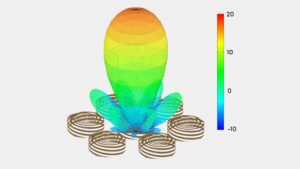
Figure 4. An example of combining the antenna elements of a 7-element CRPA to form a simple beam pointing directly overhead
The following plots illustrate CRPA array performance with the blue line representing a desired signal where the CRPA array provides a beam peak, and the red line(s) representing jammers where the CRPA array provides a null.
Each of the three plots show a different arrangement of desired and interfering paths. The beam peaks and nulls may be calculated separately for each incoming signal and updated rapidly to track the movement of the satellites, jammers, and the vehicle.
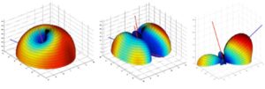
Figure 5. Illustrative beam patterns of a CRPA antenna in the presence of jamming (Source: Michael Jones, GPSWorld.com)
Technical Analysis
Digging deeper
As discussed above, CRPA systems are used with GNSS receivers to improve the overall system coverage and performance in jamming conditions. The weighted combinations of the signals from multiple antenna elements are used to achieve precise beamforming and null-steering to improve the jamming-to-signal (J/S) ratio.
Advanced receivers may include complex signal processing such as space-time adaptive processing (STAP) or space-frequency adaptive processing (SFAP) techniques to improve detection, tracking and recovery of signals in cluttered and high interference environments.
Since CRPA is an enhancement added to the receiver, it is a generic J/S improvement approach, and the CRPA design can be optimized for the specific use case being supported.
An overview of GPS signal propagation
CRPA linear array modeling
Points having equal phase, e.g., the peaks of the planewave, are drawn as parallel lines (///) in the diagram below to represent a received planewave.
The uniform linear array is the simplest example to illustrate beam-steering and null-forming principles. Figure 10, illustrates a 4-element linear array. Each of the array elements, A1-4, are fixed antennas, assumed to have an ideal omni-directional pattern; however, a unique pattern could be applied. A constant antenna spacing of dv is assumed to be ½ wavelength. In this example, a planewave is arriving with an angle of φ from the array boresight, the axis perpendicular to the array elements.
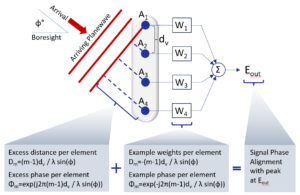
Figure 9. Illustration of a 4-element linear antenna array
Notice that there is an increasing delay to the arrival of the planewave at each of the 4 antennas with the given arrival angle. Each delay results from the distance traveled to encounter the array element. If the signal bandwidth is small as in the case of GNSS signals, then each delay can be represented by a unique phase at the center frequency, i.e., fc = C/λ.
Forming a beam in the direction of the incoming signal will maximize the received signal strength. This requires the weights to be set with a negative phase advance to that observed from the planewave, so there will be a phase alignment from each signal and they will sum to a peak.
Figure 10. Animation of an 8-element linear array in the presence of jamming signals.
Interactive beamforming plot
The beam plot of a uniform linear array is achieved by scanning the weights to evaluate pointing the beam at a range of angles, i.e. where is varied φm is varied from -90 to +90 degrees, using this equation: Φm=exp(-j2π(m-1)dv/λ sin(φ)). As expected, when the beam pointing angle matches the incoming planewave angle, there is a peak in the response.
In Figure 11 below, use the sliders to vary the number and spacing of elements and the beam pointing angle to see the resulting changes in the linear array.
λ
°
Figure 11. Interactive beamforming plot for a uniform linear array
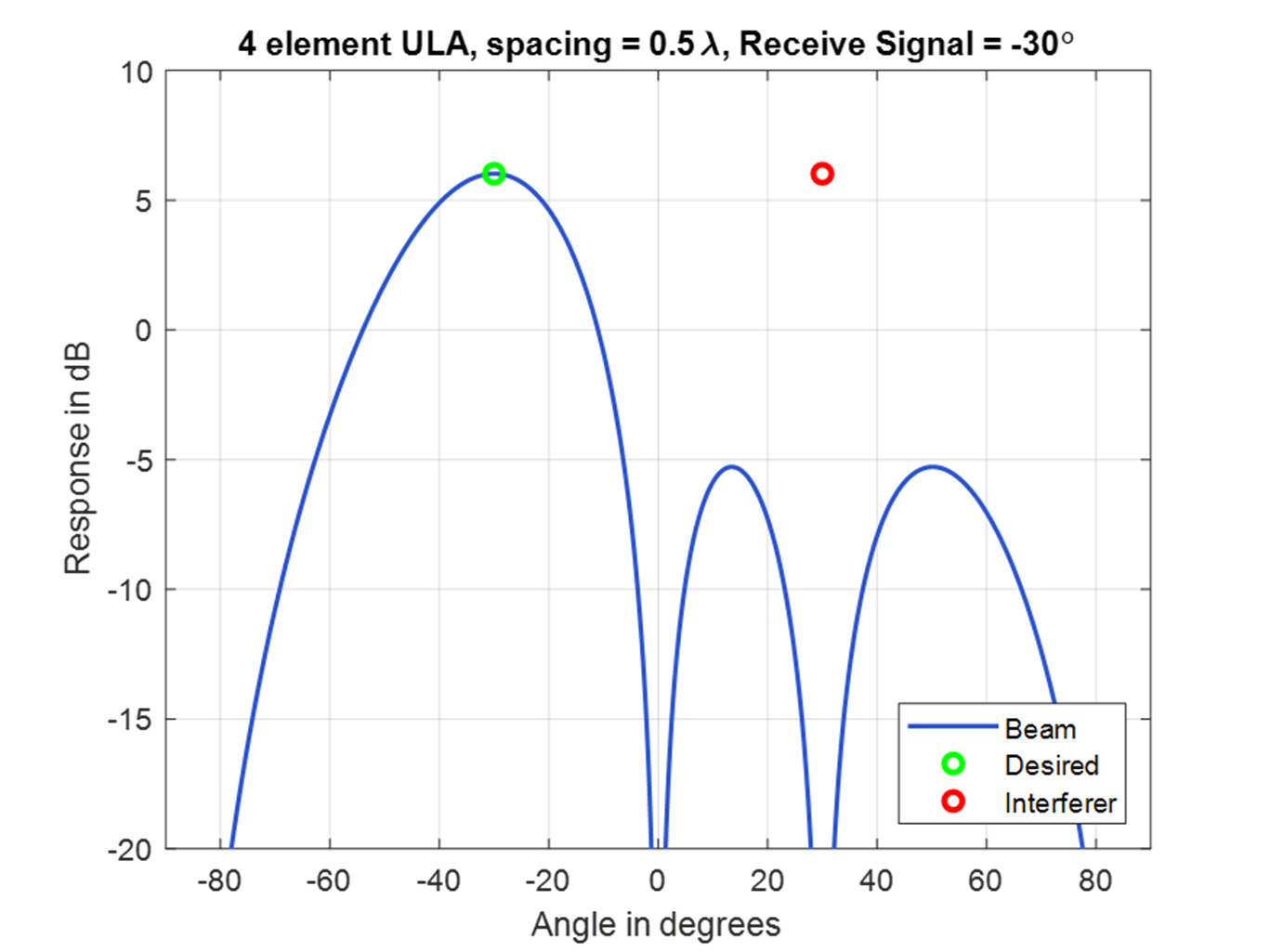
Figure 12. Linear CRPA nullsteering
Nullsteering plot
For a nullsteering example, the weights could be set in various ways to produce a null for the incoming planewave angle. In Figure 12, the weights were multiplied by [1, -1, 1, -1], so that the sum forms a null in the direction of the undesired signal at +35 deg when the desired signal is at -35 deg.
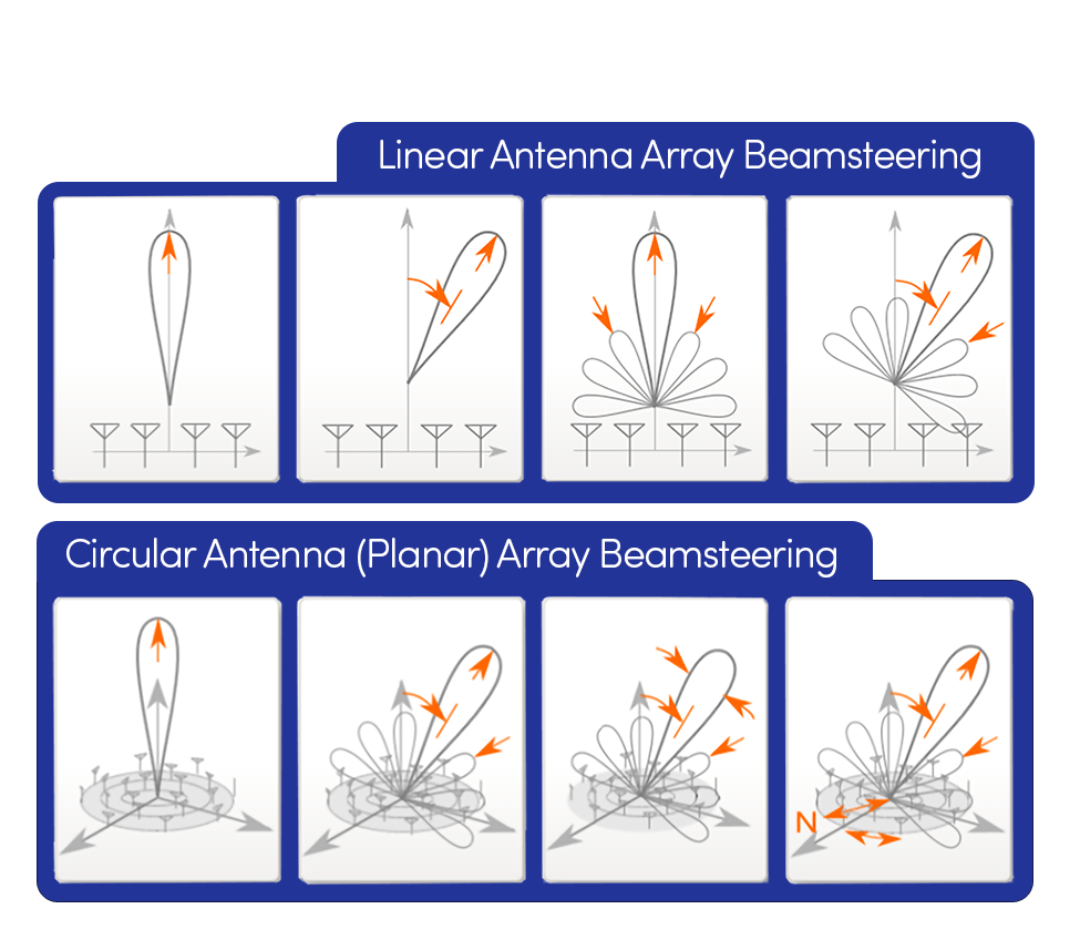
Figure 13. Linear arrays contrasted with planar arrays
Planar arrays
More complex arrays can be formed with a 2D grid of elements, called a planar array. This type of array can form a beam in azimuth and elevation and is contrasted with a linear array in Figure 13.
The array response observed from a circular pattern is based on the location of each element in the array and the complex response of each antenna. These parameters produce an amplitude and phase shift of the signal received on each element, which will be processed in the receiver to optimize the performance of the desired signal.
The beam peaks and nulls may be calculated separately for each incoming signal and updated rapidly to track the movement of the satellites, jammers, and the vehicle.
How to Test a CRPA
How to test a CRPA system
CRPA systems use antenna arrays enabled with signal processing algorithms to dynamically optimize the reception of the desired signals while simultaneously rejecting interference signals. The following graphic identifies key aspects to consider before testing a CRPA system.
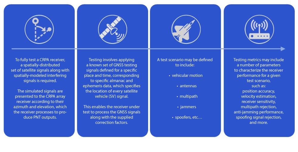
CRPA test methodologies
There are three approaches to CRPA testing; each will be discussed in turn.
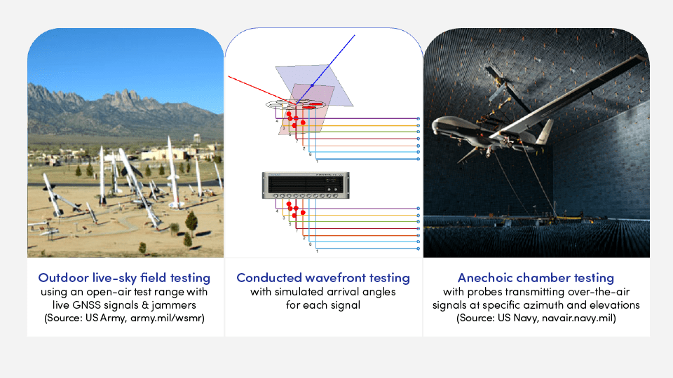
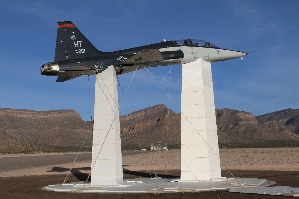
Figure 14. Live-sky testing at White Sands Missile Range in 2017 (Source : US Air Force, afmc.af.mil)
Outdoor live-sky field testing
Live sky testing validates real-world performance by using the actual outdoor signals available at the moment of testing. This provides an accurate measure of true performance, but it also implies that such a test is not repeatable since the next test at a new time will observe a different number of satellites in different locations. Also, environmental characteristics are not repeatable, such as the behavior of the multi-path scattering, and differences in the path of the measurement receiver and the presence of interference.
Figure 15. A wavefront impinging on a 4-element CRPA. Wavefront simulation requires precise phase alignment of all signals across all CRPA elements.
Conducted wavefront testing
Conducted wavefront testing models each of the SV signals at the proper azimuth and elevation observed and processed by the CRPA array. Antenna patterns at the CRPA receiver are replaced by a cabled connection to the test equipment. Measured antenna patterns with gain and phase specific to each element can be applied to each receive path to improve accuracy.
Each received planewave, which can be described as a flat wavefront having constant phase, propagates across the array and energizes each element at a specific time. Thus, there is a relative delay between the arriving signal when it is observed at each array element. These delays are proportional to a certain phase at a given frequency. For narrow band signals like GNSS it is sufficient to model each signal using the calculated phase offset to model the spatial characteristics.
Figure 16. Two planewaves encroaching on a CRPA (left), and the identical effects created through simulation (right)
In Figure 16-left, two circularly polarized planewaves are traveling from satellites at different locations in space toward the 7-element CRPA antenna. The red and blue geometric planes define points of constant E-field polarization for the propagating planewave, which defines the wavefront being observed as it intersects with the antenna array. The red planewave is shown to arrive first and contacts the array elements in order of arrival, followed by the blue planewave.
When the antenna elements are energized by the red or blue wavefront, they are illuminated to illustrate the wavefront signal contacting with each element. Then a red or blue dot representing the relative arrival time differences follows the cables associated with each antenna element. Therefore, the direction of arrival information can be observed from the relative delays indicated by the red and blue dots traveling down the wires. (Delay differences can be emulated as phase differences when the bandwidth is small as with GNSS signals.)
In Figure 16-right, the PNT X simulator is shown reproducing the signals for a CRPA test modeling the same two satellite signals being received as shown by the red and blue planewave signals. As observed, the same spatial information is present in the test signals (illustrated by the red and blue dots) representing what was observed by the CRPA antennas.
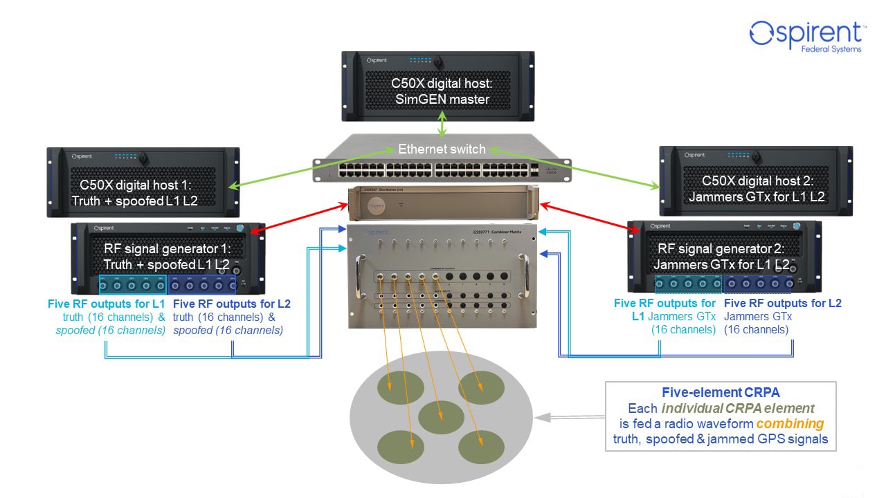
Figure 17. Flexible / scalable wavefront CRPA testing for NAVWAR: GNSS signals, jamming, & spoofing (Click to view full scale)
Conducted Wavefront Testing Summary
- The PNT X supports conducted CRPA testing
- Precise phase alignment
- Thermal phase stability
- High J/S levels
- Low uncorrelated noise levels
- Interference and spoofing are also available –all in a perfectly carrier-phase-aligned wavefront
- Key capabilities
- Support for 4-16 elements and more
- Support for all GNSS signals including classified signals
- >130dB J/S, BFEA
- Combine with (multiple) instances of inertial simulation & alternative navigation
- Inject custom IQ waveforms
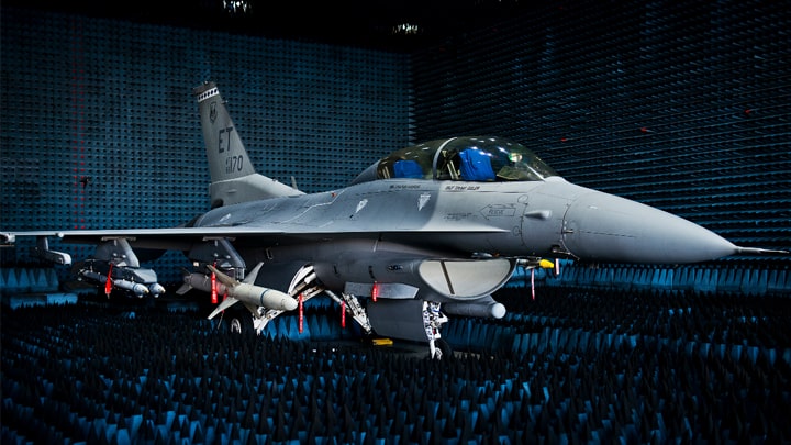
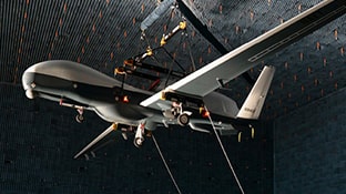
Figure 18. A F-16 under test in an anechoic chamber at Eglin Air Force Base, Florida (Source: US Air Force, eglin.af.mil)
Anechoic chamber testing
Anechoic Chamber testing uses simulated GNSS signals transmitted over-the-air using probes inside the chamber. This enables testing of the full receiver with its CRPA antennas included so that all aspects of the device-under-test is evaluated. Since the probes are at specific locations in the chamber, this produces a spatial model for the SV signal that includes and azimuth and elevation, so the probes can be used to represent satellite locations in the sky.
Fixed probes cannot replicate the movement of satellites across the sky, so a fixed probe arrangement is limited to a short simulation time before it would no longer accurately represent the SV locations.
Spirent’s patented zoned chamber
A more advanced zoned chamber approach is used to distribute a number of probes across the visible region, which encompasses the upper hemisphere. In this case, 13 or 31 probes are used to define zones. The larger number enables a finer resolution. Each zone quantizes the area to a probe, so that probe transmits one or more SV signals, and as time advances the signal representing each SV may be switched to another zone to represent its movement.
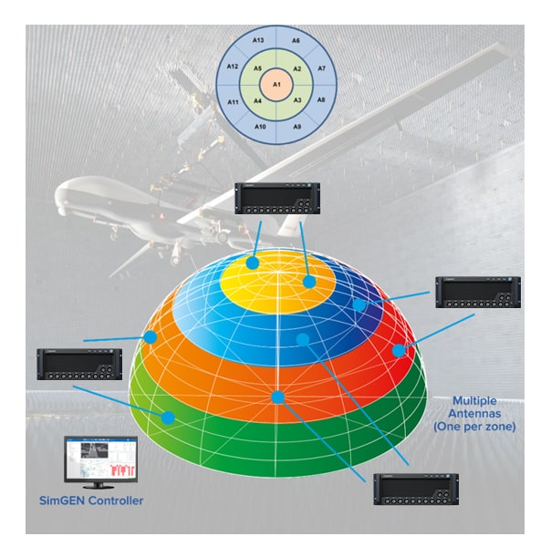
Figure 19. Spirent’s patented zoned anechoic chamber approach to CRPA testing provides day-long test durations and unmatched realism
Chamber Testing Summary
- PNT X supports anechoic chamber testing, i.e., testing the CRPA including the antenna
- Option 1 employs fixed antenna array
- Option 2 leverages Spirent’s patented zoned chamber
- The zoned chamber enables simulation of the motion of the satellites as they orbit—enabling long scenario durations and high degree of realism
- Spoofers, jammers, multipath can be simulated as well
- Spirent can simulate DUT motion through rate table or via SimINERTIAL
Test Considerations
Spirent CRPA Testing Solutions
To ensure the highest levels of reliability and integrity, CRPA systems must be thoroughly tested in a wide range of real-world scenarios. Spirent PNT X is uniquely engineered to exceed the complex requirements of current and future CRPA system testing:
- Architecture. PNT X is purpose designed using expertise honed by decades of experience and innovation. Ultra-low phase noise and unrivaled pseudorange accuracy provide the most realistic environment for testing CRPA systems, even in high-dynamic and high-jerk scenarios. Using a substandard architecture in CRPA testing can lead to inaccurate test results, false conclusions regarding resiliency and performance, and failure in the field.
- High-fidelity capability. In wavefront CRPA testing, signal carrier and code phase alignment are critical. High-quality phase alignment is particularly important for testing multi-element antennas like CRPAs.
- If a simulator needs continuous monitoring and run-time corrective adjustments to the signal to remain phase-aligned, it is a fundamentally flawed approach for applications such as CRPA testing that require aligned signals for precision wavefronts.
- When phase-alignment calibration occurs during the test, it introduces considerable phase noise that impacts the performance of the simulator and could skew test results.
- Spirent solutions are calibrated once before the start of a scenario. The wavefront is precisely calibrated, and performance is maintained for the entire test.
- Scalability. Using a scalable architecture like PNT X ensures an existing solution can easily grow to test additional antenna elements as systems evolve.
- Encrypted signals. For 40 years, Spirent has been the trusted test partner for testing restricted GNSS signals, including GPS MNSA M-Code and Galileo PRS.
- EGI/IMU signal simulation. The SimINERTIAL software module enables you to integrate simulated signals from inertial sensors into test scenarios, allowing you to characterize the performance of an integrated or embedded GNSS/Inertial solution.
To learn more, read our white paper, Characterizing CRPA and Other Adaptive Antennas, or contact us to schedule a demonstration.