Executive Summary
Overview
Controlled reception pattern antennas (CRPAs) — also referred to as anti-jam antennas — are a critical frontline technology for keeping positioning systems accurate and reliable in hostile NAVWAR (navigation warfare) environments. Whether you’re defending a vessel, guiding an aircraft, or hardening land navigation systems, CRPAs enable receivers to acquire and track authentic signals while suppressing or rejecting jamming and spoofing signals.
This page will take you from the big picture down to an accessible explanation of the mechanics:
- Why CRPAs matter
- How CRPAs work
- Signal deep dive
- Why testing is mission-critical
- How to test
Introductory Principles
Figure 1. Modeled GPS satellite orbits
What is GNSS?
Global Navigation Satellite Systems (GNSS) are satellite-based networks that provide positioning, navigation, and timing (PNT) services worldwide.
One of the most well-known GNSS systems is GPS, which guides everything from smartphones and vehicles to advanced military platforms. Modern receivers can detect and use GPS signals to pinpoint positions within meters, or even centimeters with advanced techniques.
Each GNSS satellite continuously broadcasts a radio signal containing precise location and timing information. By the time these signals reach Earth, they are millions of times weaker than a typical Wi-Fi signal — which makes them easy to block (jam) or fake (spoof).
What is a CRPA and why use it?
For systems that rely on GNSS in critical missions, resilience under all types of signal interference and environmental challenges is essential. That is where CRPAs come in. These advanced, adaptive antennas filter out jamming, detect fake spoofed signals, and focus receiver tracking towards the real GNSS “truth” signals — all in real-time. In GPS-contested situations, known as NAVWAR, CRPAs are an essential anti-jamming, anti-spoofing technology that can be the difference between mission success or failure.
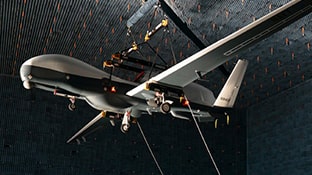
A CRPA is made up of multiple small antennas called antenna elements, which work together as an antenna array. These elements are spaced evenly and combine incoming radio signals to function like one single, steerable antenna. The signals from each element are sent to the antenna electronics (AE) unit, which processes them. This AE unit can either be built into the same housing as the antenna array or placed separately, depending on the use case.
The number of elements typically varies from 4 (minimum for effective anti-jam protection) to 16, but large specialized CRPAs with 20+ elements are being developed. One common CRPA implementation is a 7-element design, with one center antenna and 6 arranged around it. For GNSS applications, the antenna array would typically be located on top of a vehicle with the field of view pointing to the sky.
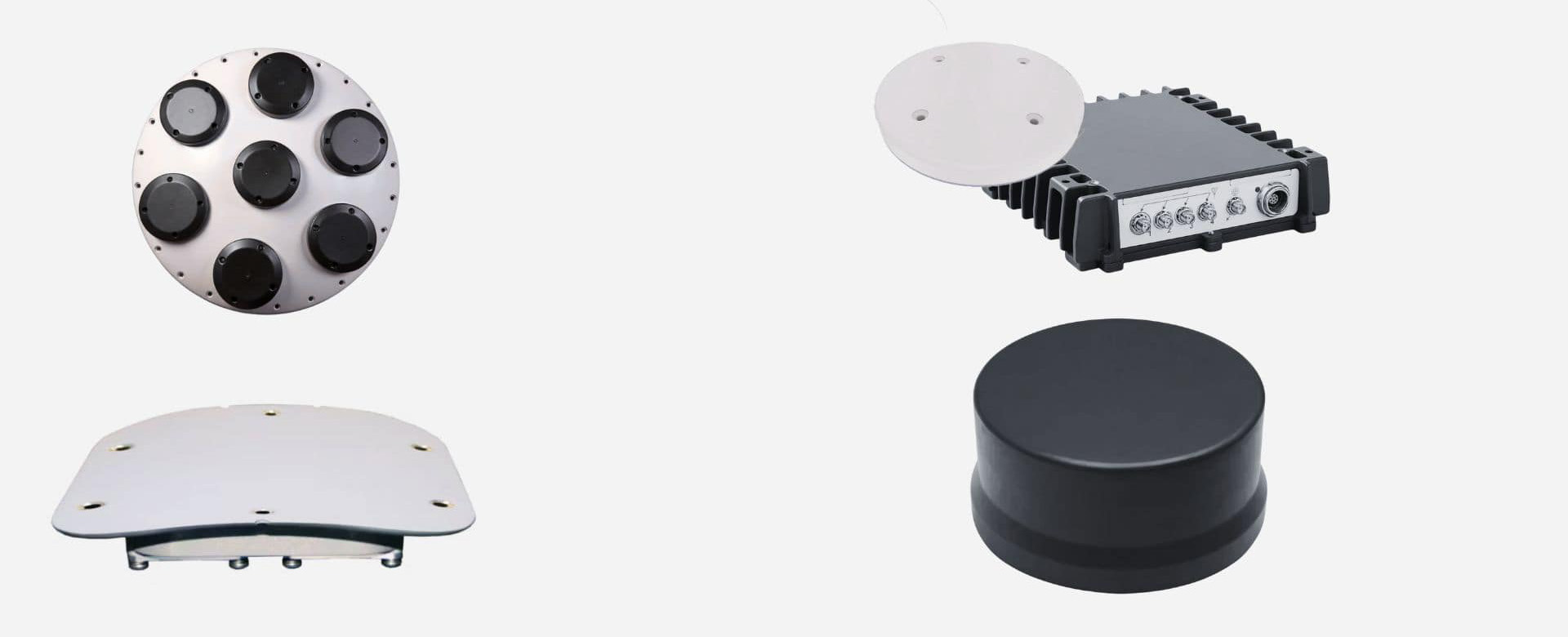
Top: A representative CRPA array with 7 antenna elements
Bottom: A conformal CRPA designed to fit aircraft fuselage
Top: A 4-element antenna and separate antenna electronics (AE) unit
Bottom: An integrated CRPA with antenna and AE in one
How does a CRPA work?
A CRPA improves GNSS receiver performance by using an adaptive array of antenna elements.
Single antenna vs. array
- A single-element antenna has a fixed reception pattern at a given frequency.
- A CRPA, by contrast, dynamically adjusts its reception patterns by combining signals from multiple elements.
How the array adapts
- The antenna electronics apply weights—adjustable values that modify each signal’s amplitude (signal strength) and phase (timing or wave alignment)—to the RF signals received at each element..
- These weighted signals are combined to form a new reception pattern.
- The pattern is optimized to:
- Amplify desired GNSS signals: beamforming
- Suppress interference/jammers: null steering
Result
- The CRPA dynamically “points” beams at satellites and “steers” nulls toward interference sources.
- This preserves GNSS signal tracking, even in hostile NAVWAR environments.
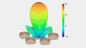
Figure 4. An example of combining the antenna elements of a 7-element CRPA to form a simple beam pointing directly overhead
The following plots illustrate CRPA array performance with the blue line representing a desired signal where the CRPA array provides a beam peak (beamforming), and the red line(s) representing jammers where the CRPA array provides a null.
Each of the three plots show a different arrangement of desired and interfering paths. The beam peaks and nulls may be calculated separately for each incoming signal and updated rapidly to track the movement of the satellites, jammers, and the vehicle.
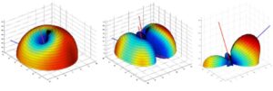
Figure 5. Illustrative beam patterns of a CRPA antenna in the presence of jamming (Source: Michael Jones, GPSWorld.com)
Technical Analysis
Digging deeper
To summarize what we have discussed so far, CRPA systems are used with GNSS receivers to improve overall system coverage and performance in NAVWAR environments. To do this, CRPAs combine signals from multiple antenna elements using carefully chosen weights—timing and power adjustments—that align the incoming signals from a desired direction. This process, known as beamforming, strengthens the desired signal. CRPA systems can also apply weights that cause destructive interference in the direction of unwanted signals, a technique known as null steering. Together, these methods improve the jamming-to-signal (J/S) ratio, making the navigation system more robust.
Advanced receivers may also use more sophisticated signal processing techniques—such as space-time adaptive processing (STAP) or space-frequency adaptive processing (SFAP)—to further enhance signal detection, tracking, and recovery in high-interference environments.
Because CRPA is an add-on to the GNSS receiver, it provides a flexible, system-level way to improve J/S performance. Its design and behavior can be tailored to the specific needs of the platform or mission it supports.
Now let’s take a closer look at the underlying mechanisms that enable CRPA systems.
CRPA linear array modeling
GNSS signals exist as a continuous RF waveform, which can be represented as a series of time slices. An RF wavefront (i.e. planewave) is how we model the slices of a continuous RF waveform which interact with CRPAs. We’ll use this model to illustrate the underlying principles of how CRPAs work and, consequently, how we test them.
The uniform linear array is the simplest example to illustrate beamsteering and null forming principles. Figure 6 illustrates a 4-element linear array. Each of the array elements, A1-4, are fixed antennas, assumed to have an ideal omni-directional pattern; however, a unique pattern could be applied. A constant antenna spacing of dv is assumed to be ½ wavelength. In this example, a planewave is arriving with an angle of φ from the array boresight, the axis perpendicular to the array elements.
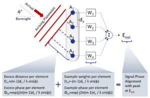
Figure 6. Illustration of a 4-element linear antenna array
Notice that there is an increasing delay to the arrival of the planewave at each of the 4 antennas with the given arrival angle. Each delay results from the distance traveled to encounter the array element. If the signal bandwidth is small as in the case of GNSS signals, then each delay can be represented by a unique phase at the center frequency, i.e., fc = C/λ.
Forming a beam in the direction of the incoming signal will maximize the received signal strength. This requires the weights to be set with a negative phase advance to that observed from the planewave, so there will be a phase alignment from each signal and they will sum to a peak.
Figure 7 depicts the behavior of an 8-element linear antenna array operating in the presence of jamming signals.
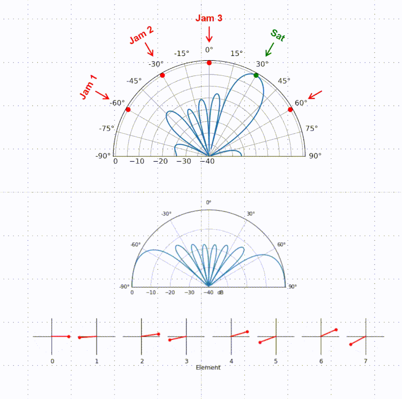
Figure 7. Animation of an 8-element linear array in the presence of jamming signals.
Interactive beamforming plot
The beam plot of a uniform linear array is achieved by scanning the weights to evaluate pointing the beam at a range of angles, i.e. where φm is varied from -90 to +90 degrees, using this equation: Φm=exp(-j2π(m-1)dv/λ sin(φ)). As expected, when the beam pointing angle matches the incoming planewave angle, there is a peak in the response.
Figure 8 is interactive: move the sliders to vary the number and spacing of elements and the beam pointing angle to see the resulting changes in the linear array.
λ
°
Figure 8. Use the sliders to change the inputs and see the resulting linear array
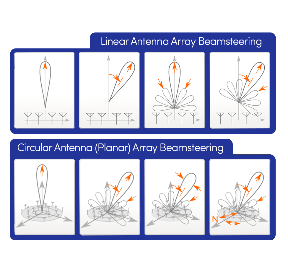
Figure 9. Linear arrays contrasted with planar arrays
Planar arrays
We have used linear arrays to simplify our discussion, but more complex arrays can be formed with a 2D grid of elements, called a planar array. This type of array can form a beam in azimuth (horizontal angle) and elevation (vertical angle) and is contrasted with a linear array in Figure 9.
The array response observed from a circular pattern is based on the location of each element in the array and the complex response of each antenna. As previously discussed, these weighted parameters produce an amplitude (signal strength) and phase shift (signal timing) of the signal received on each element, which will be processed in the receiver to optimize the performance of the desired signal.
The beam peaks and nulls may be calculated separately for each incoming signal and updated in real time to track the movement of the satellites, jammers, and the vehicle the CRPA is on.
How to Test a CRPA
Why test a CRPA system?
It is critical for developers and integrators to test a CRPA system before deployment for the following reasons:
Mission-critical applications
- CRPA systems are used in defense, aerospace, and high-stakes navigation.
- Reliable performance is essential for mission success and safety.
Need for resilience in NAVWAR
- Must operate under extreme conditions such as:
- High-power jamming
- Spoofing
- Rapid platform dynamics on munitions, aircraft, or vehicles
- Systems must be validated against corner cases to ensure robustness.
Purpose of rigorous testing
- Confirms system reliability and accuracy under real-world and worst-case scenarios
- Drives faster development and iteration to meet milestones and deadlines
- Maximizes the value of field testing by thoroughly testing in the lab first
- Ensures the system can be trusted in operational conditions
Consequences of insufficient testing
- Unverified systems can lead to:
- Mission failure
- Compromised navigation or targeting
- Loss of lives and assets
CRPA Test Methodologies
There are several approaches to CRPA testing; each will be discussed below.
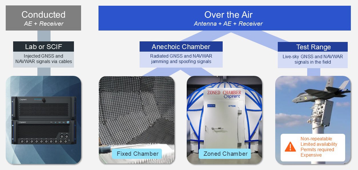
Figure 10. From left to right, testing in a lab, in an anechoic chamber, on a range
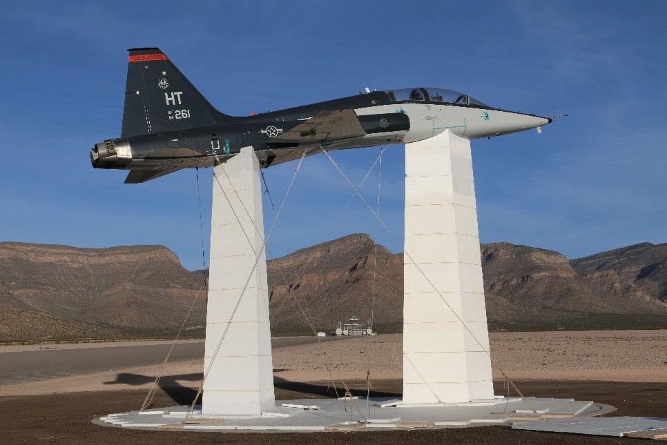
Figure 11. Live-sky testing at White Sands Missile Range in 2017 (Source : US Air Force, afmc.af.mil)
Live-sky range testing
Field testing uses live-sky satellite signals to measure system performance in the real world. It plays a critical role in validating performance, but it comes with several major drawbacks. First, tests are not repeatable or controllable: satellite positions, signal conditions, and environmental factors like multipath and interference constantly change. This makes it difficult to isolate variables or systematically compare results over time. Additionally, range testing can be costly, require permits, pose logistical challenges, and only be available infrequently during annual test events.
For these reasons, it’s important to arrive at the testing range as prepared as possible. By conducting extensive, controlled lab testing beforehand, you can maximize the value of live-sky testing, ensuring you gain the most meaningful data and stay ahead of deadlines.
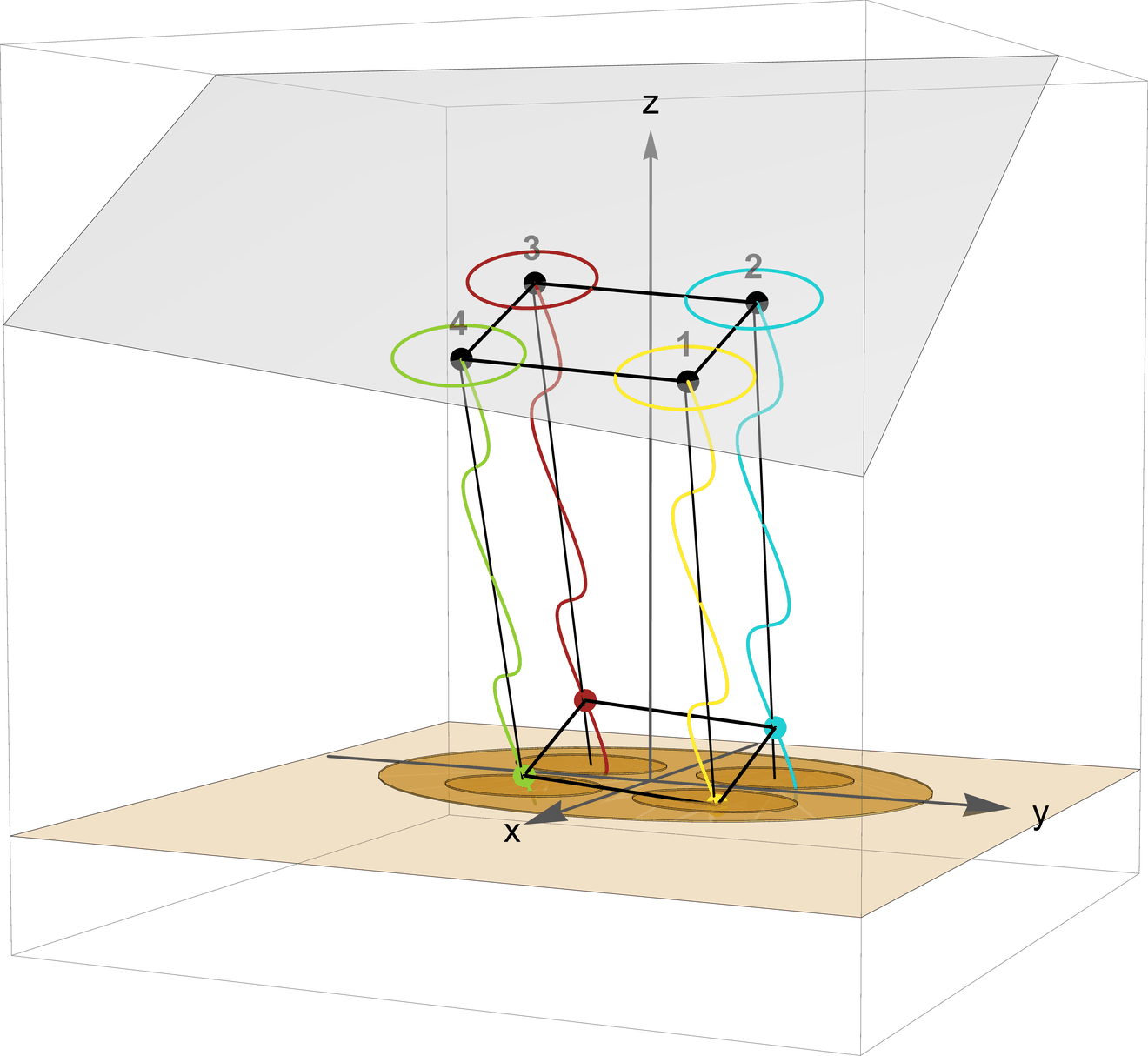
Figure 12. A wavefront impinging on a 4-element CRPA. Wavefront simulation requires precise phase alignment of all signals across all CRPA elements.
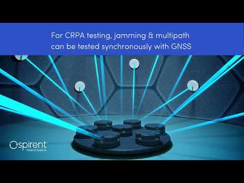
Conducted wavefront testing
Conducted wavefront testing, also known as direct injection, provides an efficient way to test CRPA systems without transmitting signals over the air. The antenna electronics (AE) are the brains of the CRPA—responsible for processing signals and applying adaptive weights—and thus are the most critical component to test. By connecting a simulator directly to the AE via cables, the physical antenna can be bypassed, enabling testing in the lab rather than in a restricted test range or anechoic chamber.
Precise wavefront simulators like Spirent PNT X model GNSS and complementary PNT signals as they would arrive from space, as well as concurrently simulating thousands of high-powered jamming and spoofing signals.
PNT X enables controlled, repeatable, in-the-lab testing of even the most complex NAVWAR scenarios, making conducted wavefront testing a flexible, scalable, and incredibly efficient way to validate CRPA performance under realistic NAVWAR conditions.
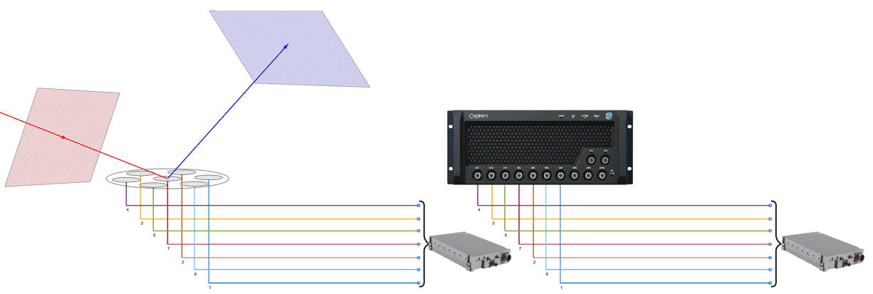
the AE receives the relative arrival time differences via cables.
and the AE receives the same information via cables.
Conducted wavefront testing models each of the satellite vehicle signals at the proper azimuth and elevation observed and processed by the CRPA array.
Figure 13 demonstrates how this process works on an array and how a simulator replicates it.
In Figure 13-Left, two wavefronts are traveling from satellites at different locations in space toward the 7-element CRPA antenna. The red and blue geometric planes define points of constant polarization for the propagating wavefront, which defines the wavefront being observed as it intersects with the antenna array. The red wavefront is shown to arrive first and contacts the array elements in order of arrival, followed by the blue.
Each received wavefront, which can be described as having constant phase, propagates across the array and energizes each element at a specific time. Thus, there is a relative delay between the arriving signal when it is observed at each array element.
When the antenna elements are energized by the red or blue wavefront, they are illuminated to illustrate the wavefront signal contacting each element. Then a red or blue dot representing the relative arrival time differences follows the cables associated with each element. The direction-of-arrival information can be observed from the relative delays indicated by the red and blue dots traveling down the wires. Delay differences can be emulated as phase differences when the bandwidth is small as with GNSS signals.
In Figure 13-Right, PNT X is shown reproducing the signals for a CRPA test modeling the same two satellite signals being received as shown by the red and blue wavefront signals. As observed, the same spatial information is present in the test signals (illustrated by the red and blue dots), replicating exactly what was observed by the antenna array.
Wavefront webinar
For more information on CRPA wavefront testing, watch the Spirent webinar, Testing, Simulation, and CRPA Innovation, on-demand now.
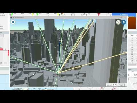
Watch a demonstration video of some of the key PNT X features for CRPA testing, including advanced NAVWAR simulation and 3D terrain modeling with multipath and obscuration
PNT X CRPA Test Solution
Accurate wavefront CRPA testing made simple.
System Architecture/Capability Overview:
Key capabilities
- Supports 4-24+ antenna elements
- 1000s of independent signals simulated simultaneously
- All GNSS + SBAS signals, including classified signals
- NAVWAR signals – jamming and spoofing
- Combine with multiple instances of inertial simulation (via SimINERTIAL) and alternative navigation
- Embedded 3D terrain modeling with real-time obscuration and multipath
- RF generation of customer waveforms from I/Q data with superimposed realism via I/Q spatial awareness
Signal performance
- Precise phase alignment: 2 degrees
- Thermal phase stability
- Continuous dynamic range of up to 140dB for unprecedented realism testing high-powered jammers
- Low uncorrelated noise levels
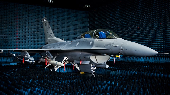
Figure 15. A F-16 under test in an anechoic chamber at Eglin Air Force Base, Florida (Source: US Air Force, eglin.af.mil)
Over the air testing
Testing in an anechoic chamber allows simulated GNSS signals to be radiated over the air (OTA) using transmitters or probes placed inside the chamber. The entire CRPA system—antenna included—can be tested and evaluated. Since the probes are at specific locations in the chamber, this produces a spatial model for the satellite vehicle (SV) signal that includes azimuth and elevation, so the probes can be used to represent satellite locations in the sky.
Fixed probes cannot replicate the movement of satellites across the sky, so a fixed-probe arrangement is limited to a short simulation time before it would no longer accurately represent the SV locations.
OTA zoned chamber
To overcome standard fixed chamber limitations, Spirent developed a patented zoned chamber solution. Independent zones simulate real-world sky view, each tied to a probe that transmits one or more SV signals. As time progresses, SV signals can switch zones to reflect movement, enabling test scenarios to run for hours instead of minutes.
This extended realism makes the zoned chamber ideal for CRPA system validation. Systems with inertial sensors can be tested in static or dynamic scenarios using a positioner. NAVWAR signals like jammers and spoofers are simulated alongside GNSS signals.
Over-the-air webinar
For more information on anechoic chamber testing for CRPA systems, watch the Spirent Federal webinar, Resilient PNT for NAVWAR & Civil Applications: Anechoic Chamber Test Innovations, on-demand now.
 Resilient PNT for NAVWAR & Civil Applications: Anechoic Chamber Test Innovations
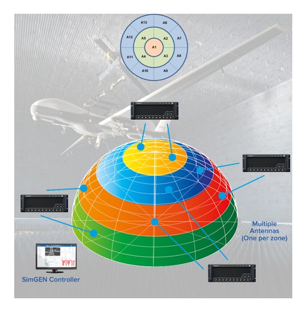
Figure 16. Spirent’s patented zoned anechoic chamber approach to CRPA testing provides day-long test durations and unmatched realism
PNT X OTA Test Solution
PNT X supports radiated OTA testing in an anechoic chamber. This allows the full system to be tested, including the antenna.
- A traditional chamber employs fixed probes with limited test times.
- Spirent’s patented zoned chamber approach increases test realism.
- The zoned chamber enables simulation of the motion of the satellites as they orbit — enabling long scenario durations and more realism.
- Spoofers, jammers, and multipath signals are simulated concurrently with GNSS.
- Spirent can simulate device-under-test (DUT) motion via:
- Rate table
- SimINERTIAL
Test Considerations
Delivering unmatched performance and accuracy in CRPA testing
To ensure the highest levels of reliability and integrity, CRPA systems must be thoroughly tested in a wide range of real-world scenarios.
Spirent PNT X is uniquely engineered to exceed the complex requirements of current and future CRPA system testing.
Architecture
- PNT X is purpose designed for NAVWAR using expertise honed by decades of experience and innovation. Ultra-low phase noise and unrivalled pseudorange accuracy provide the most realistic environment for testing CRPA systems, even in high-dynamic and high-jerk scenarios.
- Using a substandard architecture in CRPA testing can lead to inaccurate test results, false conclusions regarding resiliency and performance, and failure in the field.
High-fidelity capability
- In wavefront CRPA testing, signal carrier and code phase alignment are critical. High-quality phase alignment is particularly important for testing multi-element antennas like CRPAs.
- If a simulator needs continuous monitoring and run-time corrective adjustments to the signal to remain phase-aligned, it is a fundamentally flawed approach for applications such as CRPA testing that require aligned signals for precision wavefronts.
- When phase-alignment calibration occurs during the test, it introduces considerable phase noise that impacts the performance of the simulator and could skew test results.
- Spirent solutions are calibrated once before the start of a scenario. The wavefront is precisely calibrated, and performance is maintained for the entire test.
Scalability
- Using a scalable architecture like PNT X ensures an existing solution can easily grow to test additional antenna elements as systems evolve.
Encrypted signals
- For 40 years, Spirent has been the trusted test partner for testing classified military GNSS signals, including GPS MNSA M-Code and Galileo PRS.
EGI/IMU signal simulation
- The SimINERTIAL software module enables you to integrate simulated signals from inertial sensors into test scenarios, allowing you to characterize the performance of an integrated or embedded GNSS/Inertial solution.
To learn more, read our white paper, Characterizing CRPA and Other Adaptive Antennas, or contact us to schedule a demonstration.